Originally published on Medium.
A complete beginner-to-working-robot guide — parts, wiring, code, and app setup
This is a full build guide for a tracked robot you drive from your phone over Wi-Fi. No prior robotics experience needed. If you can follow a wiring diagram and paste code into the Arduino IDE, you can finish this in an afternoon.
By the end you’ll have a tank chassis that responds to four direction buttons and a speed slider on your phone, from anywhere on your network.
Total cost: $35–50. Total time: 3–4 hours for a first build.
What you’ll build
An ESP32 connects to your Wi-Fi and listens for commands from the Blynk app. It translates those into signals for a motor driver, which supplies power to two gear motors turning the tracks. Press forward on your phone, both tracks turn forward. Press left, they counter-rotate and the tank pivots in place.
The architecture is worth understanding before you start, because it explains every wiring decision:
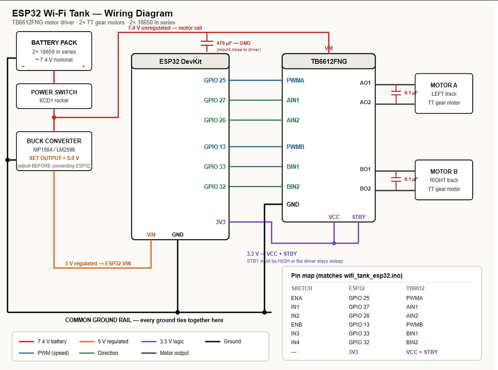
The key insight: the ESP32 never touches motor power. It only sends low-current signals telling the driver what to do. Motor current comes straight from the battery. Mixing those two paths is the single most common reason these builds fail.
Part 1: Parts list
Electronics
Item What to search for ~Cost ESP32 development board “ESP32 DevKit V1 38-pin” $5–8 Motor driver “TB6612FNG breakout module” $3–5 Tracked chassis + 2 motors “DIY tracked robot tank chassis kit TT motor” $12–25 2× 18650 batteries “protected 18650 3400mAh” $8–14 Battery holder “2x18650 holder series 7.4V” $2 18650 charger “18650 charger 2 slot” $6–10 Buck converter “MP1584EN” or “LM2596 module” $2
Small parts
Item Search for ~Cost 470 µF electrolytic capacitor “470uF 16V capacitor” $1 4× 0.1 µF ceramic capacitors “104 ceramic capacitor” $1 Jumper wires “dupont jumper wire 40pin male-female” $2 Power switch “KCD1 rocker switch” $1 Heat shrink tubing “heat shrink assortment” $3
Tools
Soldering iron and solder. A multimeter — this one is genuinely required, not optional, and I’ll explain why in Step 3. Small screwdrivers. Wire strippers. Micro-USB or USB-C cable for your ESP32.
Two notes on part selection
Get the TB6612FNG, not the L298N. The L298N appears in nearly every tutorial and it’s the wrong chip for a 3.3 V microcontroller. Its logic threshold is referenced to a 5 V rail, so 3.3 V signals sit near the boundary — sometimes fine, sometimes maddening. It also wastes about 2 V as heat, meaning a 7.4 V pack delivers roughly 5.4 V to your motors. The TB6612FNG is a MOSFET bridge designed for 3.3 V logic, drops around 0.5 V, and costs the same. Check that the board you buy breaks out the STBY pin — some clones don’t.
Confirm your chassis kit includes motors. Many listings show a complete tank and ship a plastic frame only. Read the contents list, not the photo.
Part 2: Understanding the pins
Before wiring, know what each connection does. Six signal wires run from the ESP32 to the driver — three per motor.
Sketch name ESP32 GPIO TB6612 pin Function ENA 25 PWMA Motor A speed (PWM) IN1 27 AIN1 Motor A direction IN2 26 AIN2 Motor A direction ENB 13 PWMB Motor B speed (PWM) IN3 33 BIN1 Motor B direction IN4 32 BIN2 Motor B direction
Each motor gets two direction pins and one speed pin. The direction pins work as a pair:
IN1 IN2 Result LOW HIGH Forward HIGH LOW Backward LOW LOW Coast / stop
The PWM pin then controls how fast , by rapidly switching power on and off. A value of 255 is full on, 128 is roughly half power, 0 is off.
Why these specific GPIOs
ESP32 pins are not interchangeable. These are chosen deliberately:
- GPIO 6–11 connect to the SPI flash chip. Using them prevents the board from booting.
- GPIO 34–39 are input-only. They physically cannot drive an output.
- GPIO 0, 2, 12, 15 are strapping pins, read at boot to decide startup mode. GPIO 12 pulled high is the classic “my board won’t start” trap.
GPIOs 25, 26, 27, 32, 33, and 13 avoid all of that. If you need to change one, check it against those rules first.
Part 3: Wiring
Power architecture
Two separate power paths, joined only at ground:
Battery (7.4 V) → switch ─┬─→ TB6612 VM       (motor power, direct)
                          └─→ buck → 5 V → ESP32 VIN

All grounds → one common rail
The motors get raw battery voltage. The ESP32 gets a clean regulated 5 V. They share ground and nothing else.
⚠️ Set the buck converter first
Do this before connecting the ESP32 to anything. Buck converter modules ship set to arbitrary output voltages — often 12 V.
- Connect the battery pack to the buck converter’s input
- Leave the output connected to nothing
- Probe the output terminals with your multimeter
- Turn the small trimpot until it reads 5.0 V
- Now connect the ESP32
Skipping this puts 12 V into a 5 V pin. This is why the multimeter is mandatory.
Connection list
Power
From To Battery + Switch terminal 1 Switch terminal 2 TB6612 VM and buck IN+ Buck OUT+ (5 V) ESP32 VIN ESP32 3V3 TB6612 VCC and TB6612 STBY Battery −, buck IN−/OUT−, ESP32 GND, TB6612 GND All tied to one ground rail
Signals — the six wires from the table in Part 2.
Motors
From To TB6612 AO1, AO2 Left motor terminals TB6612 BO1, BO2 Right motor terminals
The STBY pin
The TB6612 has a standby pin that must be pulled HIGH to enable the chip. Leave it floating and everything looks correct — code uploads, serial prints “Forward” — and nothing moves. Tie it to 3.3 V.
This is the number one cause of “my tank does nothing.”
Capacitors are not optional
Brushed DC motors generate substantial electrical noise. Without filtering, the ESP32 will randomly reboot the instant the tracks start moving — a symptom that looks exactly like a firmware crash and has nothing to do with your code.
- 0.1 µF ceramic soldered directly across each motor’s two terminals, at the motor , not on the breadboard
- 470 µF electrolytic across the driver’s VM and GND, mounted close to the driver (mind the polarity — the stripe is negative)
Some builders add two more 0.1 µF caps from each motor terminal to the motor casing. Worth doing if you have leftovers.
A note on breadboards
Breadboards are fine for the six signal wires. They’re not fine for the motor power path — contacts handle roughly 1 A before heating, and TT motors draw well past that when stalled. Solder the VM line and the motor outputs, or use screw terminals.
Part 4: The code
Arduino IDE setup
- Install the Arduino IDE
- File → Preferences → Additional Board Manager URLs , add: https://espressif.github.io/arduino-esp32/package_esp32_index.json
- Tools → Board → Boards Manager , search “esp32”, install the Espressif package
- Tools → Manage Libraries , search “Blynk”, install the official Blynk library
- Tools → Board , select “ESP32 Dev Module”
The sketch
/*
  ESP32 Wi-Fi controlled tank
  Motor driver: TB6612FNG (also works with L298N)
  Control platform: Blynk IoT
*/


#define BLYNK_TEMPLATE_ID   "YOUR_TEMPLATE_ID"
#define BLYNK_TEMPLATE_NAME "WiFi Tank"
#define BLYNK_AUTH_TOKEN    "YOUR_DEVICE_AUTH_TOKEN"


#define BLYNK_PRINT Serial


// Detect a dropped link in ~5 s instead of the ~10 s default.
#define BLYNK_HEARTBEAT 5


#include <WiFi.h>
#include <BlynkSimpleEsp32.h>


char ssid[] = "YOUR_WIFI_NAME";
char pass[] = "YOUR_WIFI_PASSWORD";


constexpr uint8_t IN1 = 27;
constexpr uint8_t IN2 = 26;
constexpr uint8_t ENA = 25;  // PWM, left motor
constexpr uint8_t IN3 = 33;
constexpr uint8_t IN4 = 32;
constexpr uint8_t ENB = 13;  // PWM, right motor


constexpr uint32_t PWM_FREQ_HZ    = 1000;
constexpr uint8_t  PWM_RESOLUTION = 8;     // 0-255


bool forwardPressed  = false;
bool backwardPressed = false;
bool leftPressed     = false;
bool rightPressed    = false;


uint8_t motorSpeed = 180;              // 0-255
constexpr uint8_t MIN_MOVE_PWM = 60;   // below this, motors just buzz


/*
  PWM compatibility shim.


  ESP32 has no analogWriteRange()/analogWriteFreq() -- those are ESP8266 API.
  Arduino-ESP32 core 3.x uses ledcAttach(pin, freq, res); core 2.x uses
  ledcSetup(channel, ...) + ledcAttachPin(). This covers both.
*/
#if ESP_ARDUINO_VERSION_MAJOR >= 3


void pwmAttach(uint8_t pin) {
  ledcAttach(pin, PWM_FREQ_HZ, PWM_RESOLUTION);
}


void pwmWrite(uint8_t pin, uint8_t duty) {
  ledcWrite(pin, duty);
}


#else


void pwmAttach(uint8_t pin) {
  const uint8_t channel = (pin == ENA) ? 0 : 1;
  ledcSetup(channel, PWM_FREQ_HZ, PWM_RESOLUTION);
  ledcAttachPin(pin, channel);
}


void pwmWrite(uint8_t pin, uint8_t duty) {
  ledcWrite((pin == ENA) ? 0 : 1, duty);
}


#endif


enum class Movement { Stop, Forward, Backward, Left, Right };
Movement currentMovement = Movement::Stop;


void updateMovement();
void driveForward();
void driveBackward();
void turnLeft();
void turnRight();
void stopMotors();
void setMotorSpeed(uint8_t leftSpeed, uint8_t rightSpeed);
void setMovement(Movement movement);


/*
  Blynk virtual pins
  V0 = Forward   V1 = Backward   V2 = Left   V3 = Right
  V4 = Speed slider, 0-255
*/


BLYNK_WRITE(V0) { forwardPressed  = param.asInt() == 1; updateMovement(); }
BLYNK_WRITE(V1) { backwardPressed = param.asInt() == 1; updateMovement(); }
BLYNK_WRITE(V2) { leftPressed     = param.asInt() == 1; updateMovement(); }
BLYNK_WRITE(V3) { rightPressed    = param.asInt() == 1; updateMovement(); }


BLYNK_WRITE(V4) {
  motorSpeed = constrain(param.asInt(), 0, 255);
  updateMovement();
}


BLYNK_CONNECTED() {
  // Speed only. Syncing the direction buttons would replay a stale
  // "pressed" value and drive the tank off the moment it reconnects.
  Blynk.syncVirtual(V4);
}


void setup() {
  Serial.begin(115200);
  Serial.println();
  Serial.println("Starting Wi-Fi tank...");


  pinMode(IN1, OUTPUT);
  pinMode(IN2, OUTPUT);
  pinMode(IN3, OUTPUT);
  pinMode(IN4, OUTPUT);


  pwmAttach(ENA);
  pwmAttach(ENB);


  stopMotors();


  Blynk.begin(BLYNK_AUTH_TOKEN, ssid, pass);
}


void loop() {
  Blynk.run();


  // Failsafe: stop if the link to Blynk drops.
  if (!Blynk.connected() && currentMovement != Movement::Stop) {
    forwardPressed = backwardPressed = leftPressed = rightPressed = false;
    setMovement(Movement::Stop);
  }
}


void updateMovement() {
  // Priority if multiple buttons are held: forward, backward, left, right.
  if (forwardPressed)       setMovement(Movement::Forward);
  else if (backwardPressed) setMovement(Movement::Backward);
  else if (leftPressed)     setMovement(Movement::Left);
  else if (rightPressed)    setMovement(Movement::Right);
  else                      setMovement(Movement::Stop);
}


void setMovement(Movement movement) {
  switch (movement) {
    case Movement::Forward:  driveForward();  break;
    case Movement::Backward: driveBackward(); break;
    case Movement::Left:     turnLeft();      break;
    case Movement::Right:    turnRight();     break;
    case Movement::Stop:
    default:                 stopMotors();    break;
  }


  if (movement != currentMovement) {
    currentMovement = movement;
    switch (movement) {
      case Movement::Forward:  Serial.println("Forward");  break;
      case Movement::Backward: Serial.println("Backward"); break;
      case Movement::Left:     Serial.println("Left");     break;
      case Movement::Right:    Serial.println("Right");    break;
      case Movement::Stop:
      default:                 Serial.println("Stopped");  break;
    }
  }
}


void setMotorSpeed(uint8_t leftSpeed, uint8_t rightSpeed) {
  if (leftSpeed  > 0 && leftSpeed  < MIN_MOVE_PWM) leftSpeed  = MIN_MOVE_PWM;
  if (rightSpeed > 0 && rightSpeed < MIN_MOVE_PWM) rightSpeed = MIN_MOVE_PWM;


  pwmWrite(ENA, leftSpeed);
  pwmWrite(ENB, rightSpeed);
}


void driveForward() {
  digitalWrite(IN1, LOW);  digitalWrite(IN2, HIGH);
  digitalWrite(IN3, HIGH); digitalWrite(IN4, LOW);
  setMotorSpeed(motorSpeed, motorSpeed);
}


void driveBackward() {
  digitalWrite(IN1, HIGH); digitalWrite(IN2, LOW);
  digitalWrite(IN3, LOW);  digitalWrite(IN4, HIGH);
  setMotorSpeed(motorSpeed, motorSpeed);
}


void turnLeft() {
  // Left motor backward, right motor forward
  digitalWrite(IN1, HIGH); digitalWrite(IN2, LOW);
  digitalWrite(IN3, HIGH); digitalWrite(IN4, LOW);
  setMotorSpeed(motorSpeed, motorSpeed);
}


void turnRight() {
  // Left motor forward, right motor backward
  digitalWrite(IN1, LOW);  digitalWrite(IN2, HIGH);
  digitalWrite(IN3, LOW);  digitalWrite(IN4, HIGH);
  setMotorSpeed(motorSpeed, motorSpeed);
}


void stopMotors() {
  pwmWrite(ENA, 0);
  pwmWrite(ENB, 0);
  digitalWrite(IN1, LOW); digitalWrite(IN2, LOW);
  digitalWrite(IN3, LOW); digitalWrite(IN4, LOW);
}
Three design decisions worth explaining
The PWM shim. Arduino-ESP32 changed its PWM API between core 2.x and 3.x. Older tutorials use ledcSetup() with manual channel numbers; current cores use pin-based ledcAttach(). The #if block means the sketch compiles either way, so you don’t have to care which version you installed.
Not syncing the direction buttons. On reconnect, Blynk can replay each widget’s last known value. For a momentary button that was pressed when your Wi-Fi dropped, that means the tank starts driving the moment it comes back online with nobody touching the phone. Only the speed slider gets synced.
The minimum PWM floor. Below a certain duty cycle, motors receive power but not enough torque to overcome friction — they hum and stay put, which drains the battery and sounds alarming. MIN_MOVE_PWM bumps any non-zero speed up past that threshold.
Part 5: Blynk app setup
- Create a free account at blynk.cloud
- Templates → New Template. Name it “WiFi Tank”, hardware ESP32, connection Wi-Fi
- Open the Datastreams tab and create five virtual pins:
Pin Name Type Range V0 Forward Integer 0–1 V1 Backward Integer 0–1 V2 Left Integer 0–1 V3 Right Integer 0–1 V4 Speed Integer 0–255
- Search → New Device → From template. This generates your auth token
- Copy BLYNK_TEMPLATE_ID and BLYNK_AUTH_TOKEN into the top of the sketch, along with your Wi-Fi name and password
- In the mobile app , open the device and add widgets: four Buttons mapped to V0–V3, one Slider mapped to V4
Critical: set each button to PUSH mode, not SWITCH. Push means it sends 1 while held and 0 on release. Switch mode latches — press forward once and the tank drives until you press again.
Part 6: First run
Follow this order. Don’t skip ahead.
- Buck converter set to 5.0 V , verified with a meter, nothing downstream
- Grounds wired first , everything to one rail
- Flash the sketch , open Serial Monitor at 115200 baud
- Confirm you see the Blynk connection banner. If Wi-Fi fails, Blynk.begin() blocks forever and you’ll see nothing further — that’s your signal to check credentials
- Put the chassis on blocks , tracks off the ground
- Test each direction. Confirm the serial output matches what the tracks actually do
- Sweep the speed slider, find where the motors reliably start turning
- Only now put it on the floor
If a track runs backward, swap that motor’s two output wires. Don’t fix it in code — you’ll confuse yourself later.
Troubleshooting
Symptom Likely cause Nothing moves, serial prints correctly STBY floating — tie it to 3.3 V ESP32 reboots when motors start Missing capacitors, or motor power routed through the ESP32 One motor works, the other doesn’t Enable pin on a non-PWM-capable GPIO, or a broken solder joint Board won’t boot at all Something connected to GPIO 6–11 or 12 Motors hum but don’t turn Speed set below the stall threshold — raise MIN_MOVE_PWM Tank drives off on reconnect Buttons set to SWITCH mode instead of PUSH Compile error on ledcAttach / ledcSetup Core version mismatch — the shim should prevent this, check your board package version Won’t connect to Wi-Fi ESP32 is 2.4 GHz only. It cannot see a 5 GHz network
Where to take it next
- Trim calibration. No two motors are identical, so the tank drifts on long straight runs. Add a per-side PWM scaling factor.
- OTA updates. Unscrewing the chassis to reflash gets old by the third iteration.
- Current sensing on the motor rail, so a jammed track shuts down instead of cooking the driver.
- An ultrasonic sensor on the front for obstacle avoidance.
- A proper app-side heartbeat. The current failsafe catches a dropped connection, but not a frozen phone holding an open socket. Fixing that needs a timer widget pinging a virtual pin, since momentary buttons only transmit on press and release.
Safety notes
Lithium cells are not toys. Use protected 18650s from a reputable seller, charge them in a proper charger, never leave them charging unattended, and don’t puncture or short them.
7.4 V exceeds the nominal rating of most TT gear motors (3–6 V). At the PWM levels here it’s fine, but don’t hold full speed indefinitely. Capping motorSpeed around 200 in software is cheap insurance.
Questions or a build of your own? I’d like to see it.